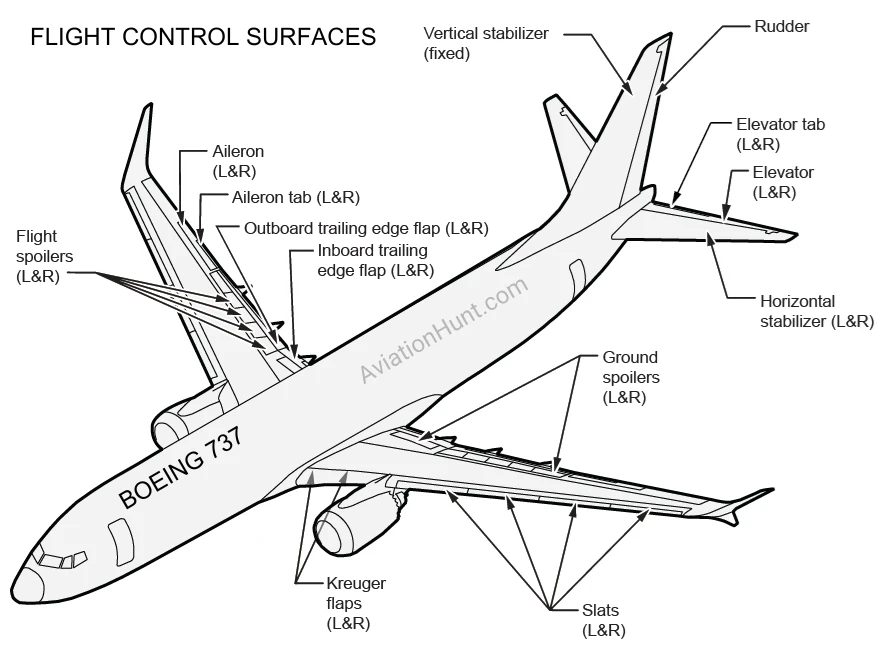
The primary flight control surfaces of the Boeing 737 include ailerons, spoilers, rudder, and elevators. The secondary flight control surfaces include the horizontal stabilizer, wing flaps and leading edge devices, and speed brakes.


Primary Flight Controls
- Ailerons: Located on the trailing edge of each wing, these surfaces control the roll of the aircraft by moving in opposite directions, allowing the plane to tilt its wings and turn.
- Spoilers: Positioned on the upper surface of the wings, spoilers assist with descent and roll control by reducing lift and increasing drag.
- Rudder: Located on the vertical stabilizer at the tail, the rudder controls the aircraft’s yaw, enabling it to turn left or right.
- Elevators: Found on the horizontal stabilizer at the tail, elevators control the pitch, allowing the aircraft to climb or descend.
The flight crew controls the ailerons and spoilers using the control wheels. The rudder and elevators are controlled by the flight crew using the rudder pedals and control columns, respectively. Cables connect the flight compartment controls to the associated components.
The spoilers are controlled by an electronic control system that operates hydraulic actuators for each spoiler. Six spoilers near the trailing edge of each wing just forward of the trailing edge flaps provide lateral control, aerodynamic braking, and lift reduction. During flight, only the second, third, fourth, and fifth most inboard spoilers can be deployed. These are referred to as “flight spoilers.” During ground operation, all spoilers can be deployed. The first and sixth spoilers, which can be deployed only during ground operations, are referred to as “ground spoilers.”
The ailerons, spoilers, rudder, and elevators are powered by the A and B hydraulic systems. If both hydraulic systems A and B fail, control of the ailerons and elevators reverts to manual, while the rudder is powered by the standby hydraulic system. Dedicated power control units (PCUs) modulate the inputs for each component powered by the hydraulic system.
Secondary Flight Controls
- Horizontal Stabilizer: Works in conjunction with the elevators to provide pitch control and maintain longitudinal stability.
- Wing Flaps and Leading Edge Devices: Positioned along the wings, these increase lift at lower speeds, facilitating safe takeoff and landing.
- Speed Brakes: Deployed from the upper wing surfaces, they increase drag and reduce speed, useful during descent and landing rollouts.
The horizontal stabilizer trims the airplane in the pitch axis. The stabilizer is moved by a jackscrew, which is automatically turned by an electric motor, or by the flight crew with a wheel on the control stand that is connected to the stabilizer with a cable.
A flap system comprising trailing edge flaps, leading edge Krueger flaps, and leading edge slats enhances airplane performance during takeoff and landing and low-speed operation by increasing the wing area and the wing camber.
There are nine flap settings: flap positions 0, 1, 2, 5, 10, 15, 25, 30, and 40. Flap position 0 is used during cruise. Flap positions 1, 5, 10, 15, and 25 are normally used for takeoff. Flap positions 15, 30, and 40 are normally used for landing. Flap position 2 can be used during flight when transitioning speeds after takeoff and before approach and landing.
Flap settings are selected with a lever on the control stand. This input is transmitted by cables to hydraulic drive motors. If the flap control cable breaks, hydraulic power to the drive motor is turned off, and the alternate system controls the flap position. An alternate mode enables the flaps to be positioned by switches on the aft overhead panel (P5).
The trailing edge flaps are moved by ball bearing screw actuators. Inputs for these actuators come from transverse torque tubes through gear boxes. The torque tubes are turned by the hydraulic motors. The system is mechanically controlled and powered by the B hydraulic system. If the B hydraulic system fails, electric power is used. During alternate operation, the system is electrically controlled and powered.
Leading edge Krueger flaps and leading edge slats work in conjunction with the trailing edge flaps to enhance airplane performance during takeoff and landing by increasing the wing area and the wing camber. The Krueger flaps are extended for all flap positions except for flap position 0.
During normal operation, the leading edge flaps and slats are mechanically controlled and are powered by the B hydraulic system. During alternate operation, the leading edge flaps and slats are electrically controlled and are powered by the standby hydraulic power system. Power control units in the wing-to-body fairing drive the slats through a torque tube. If the B hydraulic system pump pressure is lost in flight, a power transfer unit (PTU) supplies hydraulic power to the leading edge Krueger flaps and slats.
A lever on the control stand labeled SPEED BRAKE enables the flight crew to deploy the spoilers for aerodynamic braking and lift dumping. All flight spoilers extend when the lever is moved aft to the FLIGHT DETENT position. All spoilers are raised to their maximum position when the airplane is on the ground.
