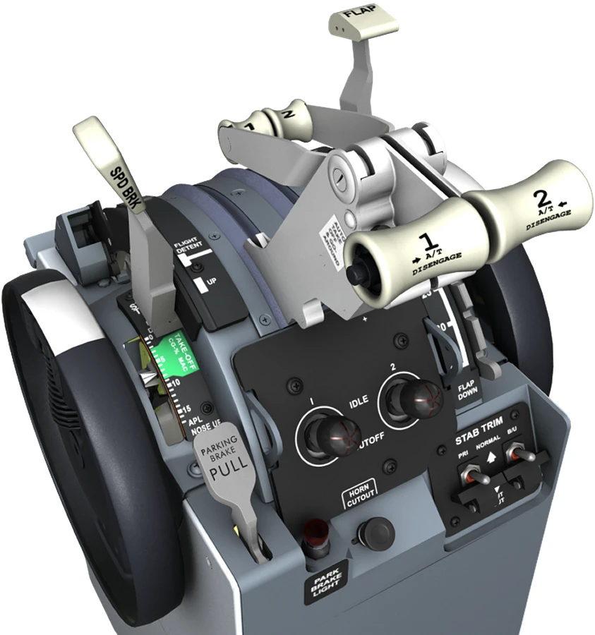
B737 Flap Lever and Position Indicator


Flap Lever
FLAP Lever
Location: Control Stand
- Selects position of flap control valve, directing hydraulic pressure for flap drive unit.
- Position of the LE devices is determined by selecting TE flap position.
- Flap lever positions 10, 15, 25, 30, and 40 arms the flap load relief system.
Flap Gates
- Prevents inadvertent flap lever movement beyond:
- Position 1: To check flap position for one engine inoperative go-around.
- Position 15: To check flap position for normal go-around.
Flap Position Indicator
Shows on the engine display.
- Indicates position of left and right TE flaps.
- Provides TE flaps asymmetry and skew indication.
FLAPS LIMIT Placard
- Indicates maximum speed for each flap setting.
- Location: MAIN PANEL – CENTER
FLAP LOAD RELIEF Light
Shows on the engine display.
- Illuminated (amber):
- If flaps are set at 40: Flaps retract to 30 due to excess airspeed.
- If flaps are set at 30: Flaps retract to 25 due to excess airspeed.
- If flaps are set at 25: Flaps retract to 15 due to excess airspeed.
- If flaps are set at 15: Flaps retract to 10 due to excess airspeed.
- If flaps are set at 10: Flaps retract to 5 due to excess airspeed.
