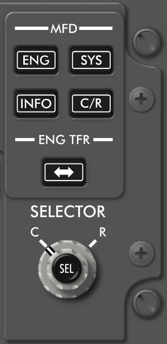
B737 MFD Panel


MFD System (SYS) Switch
- Push – SYS
- displays flight control surface position indications on an inboard or outboard display unit.
- second push removes indications from the respective display unit.
MFD Engine (ENG) Switch
- Push – ENG
- displays secondary engine indications on MDS
- second push removes secondary engine indication from MDS
Engine Transfer (ENG TFR) Switch
- Push – moves the engine indications to either the Captain’s or the First Officer’s inboard display unit.
MFD Information (INFO) Switch
Push – shows the N1/SPD REF SET display where the crew can manually enter the N1 Targets and V speed bugs on the Airspeed indicator.
There are two sections to the INFO display function. The left side allows the manual setting of the N1 thrust target. The right side allows the manual setting of V speeds, gross weight and the white bug. The radio (diamond) buttons represent the various selections. When the radio button is gray, the button is enabled and can be highlighted and selected. When the radio button is cyan, the button is disabled and cannot be highlighted or selected.
The Captain and First Officer’s Selectors on the Engine Display Control Panel are used to interact with the INFO display format. When this format is selected for display, a highlight will appear on the AUTO radio button on the N1 SET side of the display. The inner selector is used to traverse down through the N1 SET radio buttons and then to the Speed Reference radio buttons.
Only one N1/SPD REF radio button can be active at a given time. The data entry field next to the radio button is disabled when the radio button is not selected or disabled (cyan). When a radio button is selected, the corresponding entry field will become enabled (gray). When an entry field is enabled, the field can be selected (green). When the entry field is selected, turning the inner selector knob increases and decreases the value.
The speeds will increment by 1 knot per click of the selector knob. Weights will adjust by 500 kgs per click of the selector. When the weight is in metric units, the inner knob is rate sensitive for the weight entry only. Turning the inner knob slowly will increment the value by 500 kgs per detent. Turning the inner knob quickly will increment the value by 1000 kgs per detent.
SELECTOR
Each pilot has an interactive display selector that allows the crew to interact with the MFD. Each selector consists of two stacked selectors with a push select switch on top.
Outer Selector
The two position outer selector commands the cursor and highlight to a display. The (L or R) selection places the cursor on the outboard half of the inboard display. The (C) selection places the cursor on the inboard half of the inboard display unit. The (L or R) selections are only used by maintenance when going through the maintenance formats on the main displays.
Inner Selector
The sixteen detent continuously rotating inner selector has two modes of operation. The default mode of the inner selector is to control the highlight position. Turning the inner selector in the default mode moves the cursor and highlight symbol from one radio button to another. The second mode of operation is data entry. When a data entry field is selected, the inner selector will stop controlling the highlight position and will begin controlling the value inside the data entry field. If the data entry field is a number, then turning the selector will increase or decrease the number.
Select (SEL) Switch
Interactive Radio buttons on the display are selected by moving the highlight to the desired Radio button and pressing the select (SEL) switch on the selector.
